Clock Project
San Diego, CA
How it was Made:
Engineered a clock based off of an escapement wheel mechanism.
The clock was designed in Inventor, converted to AutoCAD, then transferred to Lasercamm software to be printed on 0.25 inch acrylic pieces. The base, bearings, stand, rods, and 3D printed pieces were assembled through a process of reaming, drilling, screwing, threading, and gluing.
The escapement wheel works by having a suspended weighted nut spin the escapement wheel. When the pendulum swings, it releases a tooth of the escape wheel allowing the wheel to advance or ‘escape’ by a small amount. One of the goals was to fabricate the clock so that the weight of just one suspended nut supplied enough potential energy to overcome friction and spin the escapement wheel.This goal was successfully achieved, which implied high quality construction of the clock.
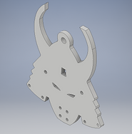
The center of mass was calculated from Inventor for the acrylic pendulum. Then 8 nails and 16 bolts were attached to the bottom of the pendulum.
Point mass analysis: the predicted time for 1 revolution of the wheel was: 7.75s
Rigid body analysis: the predicted time was 9.436s
Actual time for one revolution: 9.59s
From further analysis, it showed that the point mass analysis had -23.67% error, while the rigid body analysis had about -1.635% error. From this, it can be concluded that the rigid body analysis showed higher accuracy than the point mass analysis.
How it Works:
Analysis: